The major plight of doubts for Engineer officers onboard a
merchant ship is to tackle with electrical problems which, for most, go beyond
the understanding. It’s not always
practical to look forward to the presence of Electrical Engineer to solve the
minutest of these. It’s imperative for an engineer to understand the basic and
simple understanding of the most common parts of an electrical circuit to
head-start the fault finding in correct direction.
 |
| Power Relays – The Electromagnetic Switches |
In this discussion, the most common part of an electrical
circuit : Power relays. All across the electrical panels onboard a ship, we
find a plethora of power relays and analog timers plugged in and silently
controlling the operations of a floating giant. An understanding of these parts
can help us a lot in simplifying our fault finding skills.
Power Relays
The word Relay as defined: An electrical actuator that
allows a relatively small voltage or current to control a larger voltage or
current. In even simple language relays are nothing but an electronic switch. When a small voltage, say 24V DC, is applied to a relay it makes or breaks a 220V AC circuit. So a small 24V DC voltage controls a large 220V AC voltage. This 24V DC may be even smaller and 220V AC can be even larger.
Construction of a Relay
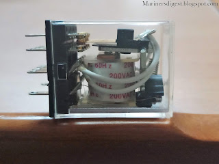
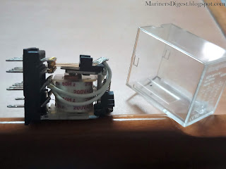
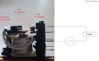
The picture shows a relay inside a plastic casing. The outer casing is just for the protection of delicate parts of this power relay. The outer plastic casing once removed and the internal parts of the relay is much easy to understand.
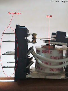
The following pictures give a view of different parts of a
relay. It consists of an electromagnetic coil and an armature. The armature is
hinged at a point across which it can move towards or away from the coil. A spring
is used on the opposite of armature across the hinge and it keeps the armature
pulled away from the coil when the coil is not energized.
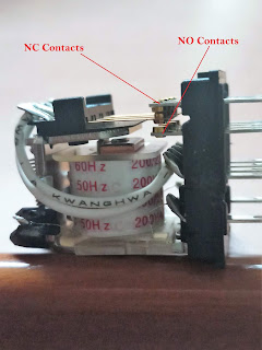
When the coil is not energized or
in de-energized state, the terminals of armature keep in contact with the NC
(Normally Closed) contacts and away from the NO (Normally Open) contacts. When
a small excitation voltage is applied to the coil terminals the
electromagnetism in the coil pulls the armature towards itself against the
spring force. When the armature is pulled down, the terminals of armature move
downwards too thus breaking the NC contacts and touching the NO contacts. The
coil can be energized with a voltage as low as 6V. The NC and NO terminal can
be used to make or break a voltage of as high as 220V.
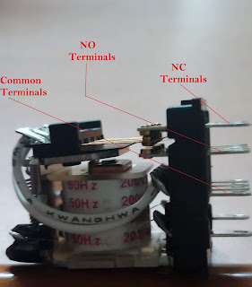 |
| Terminals of a Power Relay |
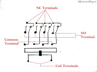
The following is the schematic diagram of power relays in both the energized
and DE-energized state.
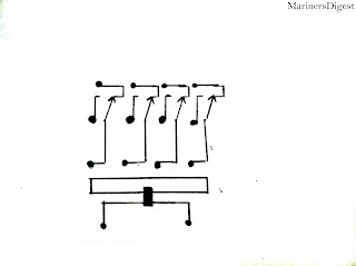 |
| Power Relay De-energized |
 |
| Power Relay energized |
Now, if a load is connected across the common and NC contact
of the relay, the following happens :
When the coil is de-energized the common terminal and NC
terminal are closed and thus the load receives the power supply.
As soon as the coil is energised the armature is pulled down
thus breaking the NC contact and the load circuit is broken. The load doesnot
receive power and hence switches off.
On the contrary, if a load is connected across the common
and NO contact of the relay, the following happens :
When the coil is de-energized, the common terminal and NO
terminal are open and thus the load circuit is broken. The load doesn’t receive
power and hence remains switched off.
As soon as the coil is energized, the armature is pulled
down thus touching the NO contact and the load circuit is energized. The load
receives power and hence switches ON.
As already explained, to energize the coil we need a
relatively small voltage and current. In lieu of that the relay’s NC and NO
contact can handle a relatively larger current and voltage. A number of different types of relay comes
with different coil and terminal parameters.
Usually the coil is energized by either a small DC supply or
a 220V AC control voltage supply. The NC, NO and Common terminals are made to
handle the usual 440V AC power supply for the load which is required to be
switched ON or off.
Here a small doubt may arise among readers, how a coil would
be energized with an AC supply. The characteristic of AC voltage to
continuously change its direction would cause a coil to continuously change
it’s polarity and thus there won’t be any change in position of armature.
An important point to understand here is the resilience of
the spring. Though the polarity of an AC coil changes at a high frequency of 60
or 50 times per second (60 Hz or 50 Hz supply), the spring has it’s own delay
time. So it can’t pull back the armature to NC contact at same rate. Hence the
armature remains pulled towards the coil.
Yet, the AC relays suffer from a characteristic noise of
chattering, because of continuously loading and unloading of spring. In
addition to it the continuously reversing force on the spring may cause it to
fail at much lesser time. To tackle these problems of an AC relay has two coils
to make a transformer. The wire of the traditional cil is the transformer
primary. The secondary of the transformer looks like a D shaped copper washer
or ring. Some magnetism from the primary coil produces current inside the
copper ring. The current in the ring or the secondary is actually delayed
compared to the current in the primary coil to keep the core always partially
magnetized. The lever, hence, won’ chatter against the core because, while the
AC is flowing, the continuously magnetized core will never release it.
While choosing a relay it is to be well understood that the
coil and terminal parameters should be well matched with the intended use of
the relay.
A DC relay should only be energized by the specified DC
voltage and the voltage against NC, NO and Common terminal should never go
beyond the rated terminal voltage. If the terminal voltage goes beyond the
rated terminal voltage the NC and NO contacts may get burnt or welded at high
temperature thus failing the switching action of the armature when the coil is
energized or DE-energized.
The following is a snapshot of different ratings of both AC
and DC relays with their coil and contact parameters
 |
| Coil and Contact parameters of a power relay |
From the above table it can be well inferred that a coil
voltage as small as 6V AC can switch 250V AC or 30V DC at the terminal. As
discussed earlier many different coil voltage can be chosen upon as given in
the table depending upon the usage. The Power relay discussed above is a four pole type relay. Meaning, this relay can be used to switch 4 power circuits at one time from single control voltage. Similarly we have 2 pole and single pole relay also.
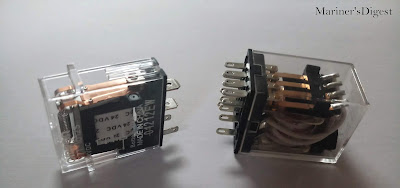 |
| Single Pole and 4 Pole power Relay |
Usually onboard a ship, relays with 220V AC coil voltage and
440 V AC terminal voltage is used. Following is few example of use of relay:
- Control signal of 220V AC signaling a relay to switch on the Boiler FD fan.
- Control Signal of 220V AC signaling a relay to start the bilge pump on receiving high level signal from float switch in the ER bilges.
The vast use of relays in almost all machineries onboard can
only be explained better by a good understanding of its working. Power relays
are small yet effective link in the control systems of machineries.



Thanking you Eastto for reading the article. I hope you liked the other articles too.
ReplyDeleteGreat explanation
ReplyDelete